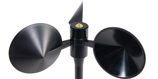


40H Hall Effect Anemometer - Connection Diagram
The 40H Anemometer uses a solid state Hall Effect transducer to convert the anemometer rotation into a square wave output. There are three terminals on the 40H indicated on the above drawing. Power must be applied to the 40H via the indicated positive (+) and negative (-) terminals. This voltage must be between 5 and 26 volts (+ 24V nominal). The output is an open collector transistor that when used with a pull-up resistor provides a square wave voltage signal output referenced to negative (-).
Related Products/Accessories
Download Calibration Reports
Our Calibration Report Retriever Tool is a comprehensive database of reports for the following products:
NRG Anemometers
110S Temperature Sensor
200M Wind Vane
200P Wind Vane
BP20 Barometric Pressure Sensor
BP60 + BP60C Barometric Pressure Sensor
HybridMC Anemometer + Vane
HybridXT Anemometer + Vane
PVT1 PV Temperature Sensor
T60 + T60C Temperature Sensor
R1 Pyranometer
R2 Pyranometer
RH5X Relative Humidity Sensor
Thies First Class Advanced Anemometer
WindSensor P2546-OPR Anemometer
Tech Support
Whether you are troubleshooting in the field or learning how to install a product, we are here for you.