


NRG 40C Anemometer - Solar
The 40C Anemometer offers field-proven measurement accuracy at an economical price.


Configuration Options
Details
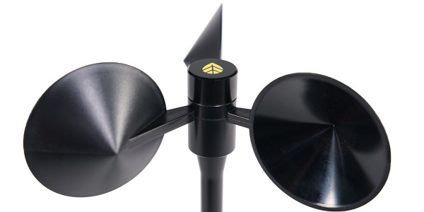
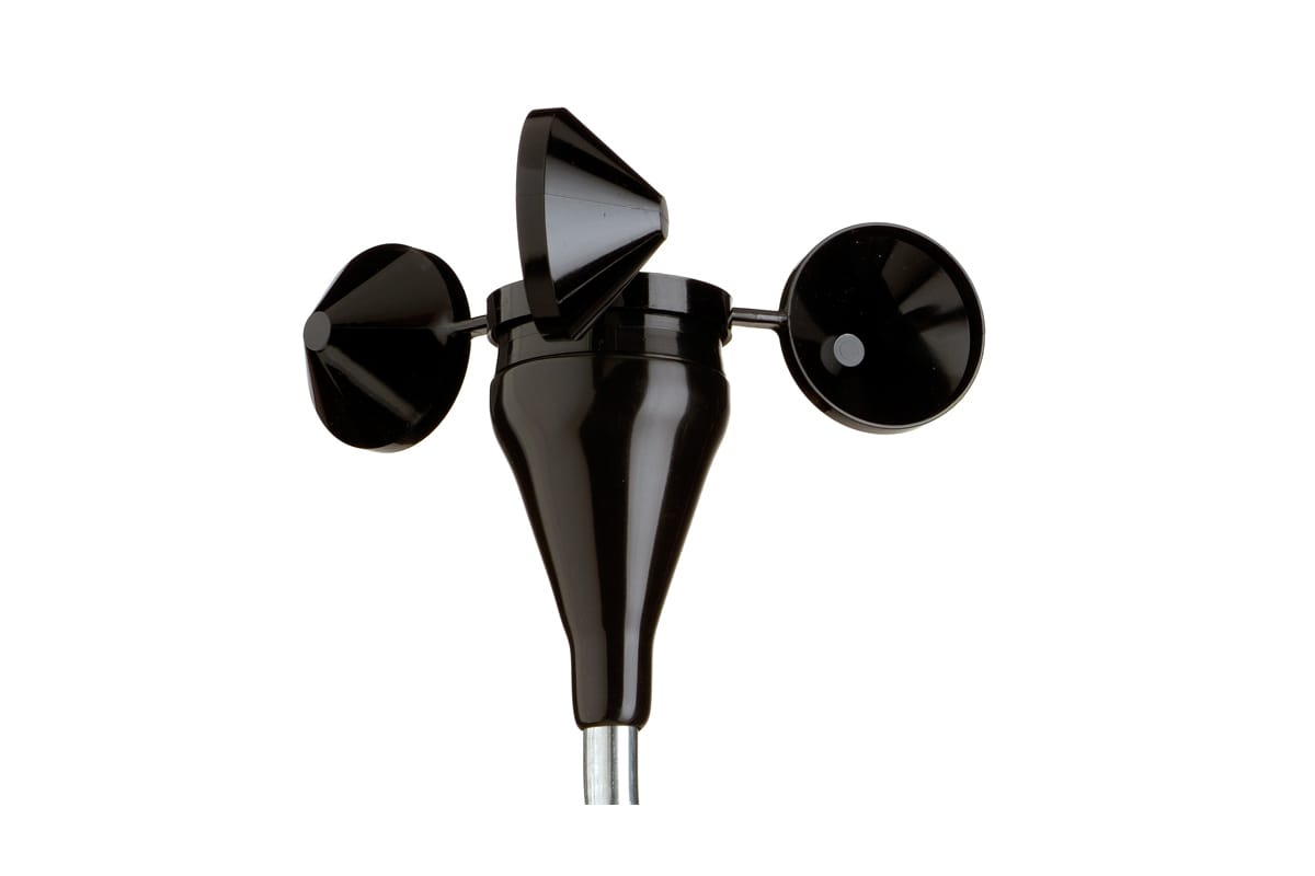
The 40C Anemometer has recorded wind speeds of 96 m/s (214 mph). Their bearings and low moment of inertia permit very rapid response to gusts and lulls. Due to their output linearity, these sensors are ideal for use with various data retrieval systems. A four-pole magnet induces a sine wave voltage into a coil, producing an output signal with frequency proportional to wind speed.
Constructed of rugged Lexan cups, the 40C is molded in one piece for repeatable performance. A rubber terminal boot is included with each anemometer for additional protection from the elements.
A MEASNET calibration certificate is available for each sensor: Download Calibration Report.
Recommended Items
Specificiations Print Specs
Product Support
Customer Service
+1 802-482-2255
Mon – Fri: 8:30am – 5:00pm Eastern Time (GMT-5)
Accessories
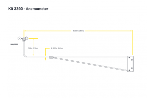
Mounting Boom | 1.53m (60.5"), Tubular - Solar
Mount your anemometers and wind vanes on NRG TallTowers™.